
Introduction: When Lightning Strikes, Will Your Building Survive?
Every second, approximately 100 lightning bolts strike the Earth’s surface. Each one carries up to one billion volts and can reach temperatures five times hotter than the surface of the sun. For most of human history, this was simply a fact of nature. Today, it is an engineering problem—one with a well-understood, deployable solution.
Modern structures face a growing vulnerability that their predecessors never had. Taller buildings reach deeper into the storm environment. Data centers, hospitals, and industrial facilities are packed with sensitive electronics that can be destroyed not just by a direct strike, but also by the electromagnetic pulse generated by a nearby strike. The financial and operational consequences of a single unprotected event can run into millions.
The lightning protection system — often reduced in popular understanding to a single rod on a rooftop — is, in reality, a carefully engineered network of three interdependent components designed to intercept a strike, safely carry its current to ground, and dissipate it harmlessly into the earth. Get any one component wrong, and the other two cannot compensate.
This guide covers everything you need to know: the physics behind why it works, the three pillars that make up a complete system, the international standards that define what “protected” actually means, and how to specify the right system for your specific building and risk profile.
| ⚡ Key Statistic A single lightning strike can carry 30,000 amperes of current. By comparison, a typical household circuit breaker trips at 15–20 amperes. The ratio is roughly 2,000:1. No unprotected structure can safely handle that load. |
The Physics of a Lightning Strike
To design a protection system that works, you first need to understand precisely what you are protecting against. Lightning is not a simple bolt from sky to ground — it is a complex, bidirectional electrochemical process that unfolds in milliseconds.
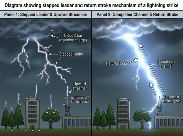
How a Strike Develops: The Stepped Leader
As a thunderstorm builds, charge separation occurs within the cloud — negative charge accumulates at the base, positive charge near the top. The negative charge at the cloud base induces a corresponding positive charge on the ground below, particularly on tall, pointed, or conductive objects.
When the electrical potential difference becomes large enough to exceed the dielectric strength of air — approximately 3 × 10⁶ volts per metre — the air begins to break down. The strike does not travel in a single straight line. Instead, a faint, invisible ionised channel called a stepped leader propagates downward from the cloud in discrete steps of 50–100 metres, pausing briefly between each.
Simultaneously, upward streamers rise from objects on the ground in response to the intensifying electric field. When a downward stepped leader connects with an upward streamer, the channel is complete — and in that instant, the enormously bright return stroke travels upward through the channel at roughly one-third the speed of light.
Point Discharge and Air Dielectric Breakdown
Sharp, pointed conductors concentrate the electric field at their tips — a phenomenon called point discharge or corona discharge. When the field strength at the tip of an air terminal exceeds 3 × 10⁶ V/m, the surrounding air ionises, creating a conductive plasma channel. This is the fundamental physics behind why lightning rods work: they create a locally favorable condition for the upward streamer to form, making the rod the most probable point of strike attachment within its protection zone.
The Path of Least Resistance
Once the lightning channel is established, current takes the path of lowest impedance from the strike point to earth. A properly designed protection system creates a deliberate, low-impedance path — with copper or aluminium conductors bonded to a deep, low-resistance earth electrode — that is orders of magnitude more conductive than the building’s structural materials. Current follows this engineered path rather than travelling through concrete, steel framing, electrical wiring, or water pipes.
This is why partial systems are dangerous. A well-placed air terminal with an inadequate earthing system will still carry a strike — but without a proper earth termination, that current has to go somewhere. It will find its own path, potentially through the building’s services, causing fire, explosion, or fatal side flashes to occupants.
Defining the Zone of Protection
Engineers use two primary methods to determine how much of a structure an air terminal protects, and where additional terminals are needed.
Rolling Sphere Method: Imagine a sphere with a radius defined by the required Lightning Protection Level (20 m for LPL I, up to 60 m for LPL IV) rolled across and around a structure. Any surface the sphere can touch is considered vulnerable and requires an air terminal. This method is particularly useful for complex rooftop geometries.
Protection Angle Method: A cone of protection is projected downward from each air terminal at a defined angle (dependent on terminal height and LPL). Structures or surfaces within the cone are considered protected. Simpler to apply on conventional buildings, but less precise for complex shapes.
Mesh Method: For large flat roofs or structures where a single terminal cannot protect the entire surface, a mesh of interconnected conductors (a Faraday cage or mesh method) is laid across the roof surface at spacings defined by the required LPL. This ensures no part of the roof is more than the maximum allowable distance from a conductor.
The Three Pillars of a Complete Protection System
Most popular articles about lightning protection focus entirely on the rod at the top of a building. This creates a dangerously incomplete picture. A lightning protection system is a chain — and every link must be engineered to the same standard. There are three distinct, irreplaceable pillars.
Pillar 1 — Air Terminals (The Interception Point)
The air terminal is the first point of contact between the lightning channel and the protection system. It must be positioned to reliably attract the upward streamer before the surrounding unprotected structure does.
Conventional Solid Rod Terminals
The classic lightning rod: a pointed copper rod mounted at the highest point of the structure. Simple, reliable, and supported by over two centuries of documented performance. IEC 62305 explicitly recognises this type and provides clear installation parameters.
Early Streamer Emission (ESE) Terminals
As per the NFC 17 – 102 standard, ESE terminals emit an upward streamer earlier than conventional terminals, thereby intercepting strikes over a larger radius.
Pillar 2 — Down Conductors (The Current Highway)
Once a strike is intercepted, 30,000 amperes of current needs to travel from the terminal to the earth electrode as quickly and safely as possible. The down conductor is that route.
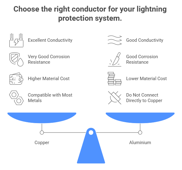
Material Choice: Copper vs. Aluminium
| Property | Copper | Aluminium |
| Conductivity | Excellent (5.96 × 10⁷ S/m) — the benchmark | Good (~60% of copper) — requires larger cross-section for equivalent performance |
| Corrosion Resistance | Very good; forms protective patina outdoors | Good in dry conditions; avoid buried/concrete contact |
| Cost | Higher material cost | Lower material cost, lighter weight |
| Compatibility | Compatible with most metals via approved connectors | Do not connect directly to copper — galvanic corrosion will occur |
| Common Applications | Preferred for all critical installations, earthing connections | Large industrial rooftops where weight and cost are key factors |
Strips vs. Round Conductor
Flat tape/strip conductors (typically 25 mm × 3 mm) are the most commonly used. They lie flat against surfaces, are easier to visually inspect, and have a larger surface area, which reduces skin-effect impedance at high frequencies—an important factor during the fast-rise time of a return stroke.
Round cable conductors are preferred where the conductor must be routed through pipes or conduit, or where the aesthetic of an exposed flat strip is unacceptable. Minimum cross-sections are specified by IEC 62305: 16 mm² for copper cable, 25 mm² for aluminium.
Routing Rules
How a down conductor is routed is as important as its material. Key requirements include:
- Minimum number of bends — each 90° bend increases impedance and the risk of side-flash
- Minimum bend radius of 200 mm — sharper bends create localised high-voltage points
- No loops — inductance in loops can produce dangerously high voltages mid-conductor
- Minimum separation from metallic services — to prevent side-flash to pipes, cables, and steelwork
- Minimum two down conductors for buildings over a certain footprint — to provide redundancy and reduce current per path
Pillar 3 — Earthing & Grounding (The Safe Destination)
The earthing system is where the energy from a lightning strike finally dissipates — dispersed as heat and electromagnetic radiation into the mass of the earth. It is, arguably, the most important and most overlooked pillar of the three.
Why Earth Resistance Matters
The voltage that develops at the earthing electrode during a strike is directly proportional to the earth resistance. A high-resistance earth means a high step-and-touch voltage — the voltage gradient across the soil surface immediately around the electrode — which can be lethal to anyone in the vicinity. It also creates a higher potential difference between the building’s earthing system and incoming services (power, data, water), driving current through those services and the equipment connected to them.
| 📐 Target Values IEC 62305 recommends an earth resistance of 10 Ω or less for lightning protection purposes. For critical facilities such as data centres, hospitals, and substations, values of 1 Ω or less are often specified. |
Types of Earth Electrode
Driven Rod Electrodes: The most common type. Copper-bonded or stainless steel rods of 1.2–3 m length driven vertically into the ground. Multiple rods can be connected in parallel to reduce resistance, but their spacing must be at least twice their length to avoid mutual interference.
Plate Electrodes: Horizontal copper or galvanised steel plates buried at 600 mm depth minimum. Effective in shallow soils where driven rods cannot achieve sufficient depth.
Ring Electrodes: A conductor laid in a horizontal ring around the building perimeter at 1 m depth. Highly effective, as it creates equipotential bonding around the entire structure and is required by IEC 62305 for larger buildings.
Chemical/Electrolytic Earthing: Electrodes filled with hygroscopic compounds that maintain low resistance even in dry, high-resistivity soils. Often used in rocky terrain, desert environments, or locations where conventional earthing consistently fails.
Soil Resistivity
The effectiveness of any earthing installation is governed by the resistivity of the local soil. Wet clay may have a resistivity of 20 Ω·m; dry granite can exceed 10,000 Ω·m. A soil resistivity survey should always precede the earthing design on any new installation. Without it, you are guessing — and if you guess wrong, the entire protection system is undermined.
International Standards Decoded
A lightning protection system is only as good as the standards it is designed and built to. Understanding the key international standards is essential — both for ensuring your system actually provides the protection it claims to, and for demonstrating regulatory compliance, insurance validity, and duty of care.
IEC 62305: The Core Framework
IEC 62305 is the international standard governing the design of lightning protection systems for structures. It is published in four parts:
- Part 1 — General Principles: Fundamental concepts, the physics of lightning, and the overall framework of risk management.
- Part 2 — Risk Management: The methodology for calculating lightning risk and determining whether protection is required, and to what level.
- Part 3 — Physical Damage to Structures and Life Hazard: Design requirements for external lightning protection systems (air terminals, conductors, earthing).
- Part 4 — Electrical and Electronic Systems within Structures: Requirements for surge protection and bonding to protect internal electronics from LEMP (Lightning Electromagnetic Pulse).
Lightning Protection Levels (LPL I–IV)
The most important output of an IEC 62305-2 risk assessment is the required Lightning Protection Level. The LPL determines every dimensional parameter of the subsequent system design — the rolling sphere radius, the mesh size for roof conductors, the minimum conductor cross-sections, and the separation distances from other services.
The table below provides a quick reference for all four protection levels:
| LPL | Rolling Sphere Radius | Mesh Size | Protection Angle (45m) | Typical Application |
| I | 20 m | 5 m × 5 m | 25° | Explosive plants, hospitals, nuclear facilities |
| II | 30 m | 10 m × 10 m | 35° | Museums, large commercial buildings |
| III | 45 m | 15 m × 15 m | 45° | Residential, offices, industrial |
| IV | 60 m | 20 m × 20 m | 55° | Low-risk agricultural structures |
| 💡 Choosing the Right LPL LPL I does not simply mean ‘better’ — it means the system will intercept a wider range of strike energies, including smaller strikes that LPL III/IV systems are designed to let pass (as the probability of smaller strikes is already captured in the risk calculation). Always base LPL selection on a formal risk assessment, not assumptions. |
IEC 62561: Component Testing Standards
Where IEC 62305 tells you how to design a system, IEC 62561 tells you what the components must survive. It covers testing requirements for all hardware elements including:
- Part 1: Requirements for connection components (IEC 62561-1:2023): Defines requirements for components like connectors, clamps, bonding components, and test joints.
- Part 2: Requirements for conductors and earth electrodes (IEC 62561-2): Specifies performance for metal conductors and earth electrodes.
- Part 3: Requirements for isolating spark gaps (ISG): Covers devices meant to isolate metallic parts from the LPS, often used for bridging or functional insulation.
- Part 4: Requirements for conductor fasteners (EN IEC 62561-4:2023): Covers metallic, non-metallic, and composite fasteners holding conductors.
- Part 5: Requirements for earth electrode inspection housings and seals (EN IEC 62561-5:2024): Details requirements for inspection housings and sealing arrangements for earth electrodes.
- Part 6: Requirements for lightning strike counters (IEC 62561-6:2023): Specifies tests for devices counting lightning strikes, including new classifications for internal circuits.
- Part 7: Requirements for earthing enhancing compounds (EN IEC 62561-7:2024): Covers materials to improve earth terminal resistance
A system built with components tested to IEC 62561 provides a documented and verifiable level of performance. A system built with untested or non-rated components may appear identical on a drawing but fail catastrophically during an actual event.
Side-Flash: The Hidden Danger
Side-flash is one of the most misunderstood risks in lightning protection, and it is a direct consequence of ignoring the standards on separation distance.
When a lightning strike travels down a protection system conductor, it generates an enormous transient voltage along the conductor’s length. If any grounded metallic object — a pipe, a steel column, a conduit — is within a certain distance of the conductor, a flashover (arc) can jump across the gap. This arc carries enough energy to ignite materials, damage equipment, and kill.
IEC 62305 specifies minimum separation distances between down conductors and all other metallic services. Where those distances cannot be maintained, equipotential bonding must be used to eliminate the potential difference. This is non-negotiable — not an optional upgrade.
Common Myths vs. Reality
Misconceptions about lightning protection are remarkably persistent — partly because lightning itself is rarely witnessed at close range, and partly because the topic sits at the intersection of physics, engineering, and folklore. Here are the most common myths encountered in the field, and the reality that replaces them.
| ❌ Common Myth | ✅ The Reality |
| Lightning rods attract strikes from miles away | They only intercept strikes already targeting the building’s immediate vicinity — they don’t increase overall risk. |
| One rod is enough for any building | Coverage depends on building height, roof surface area, and the required Lightning Protection Level (LPL I–IV). |
| A good conductor makes earthing optional | The earthing system is where all that energy must safely go. Without it, the system has nowhere to terminate. |
| Stainless steel is the best material | Conductivity matters most. Copper is far superior in electrical performance; stainless steel is often chosen for aesthetics only. |
| Lightning only strikes the tallest point | Strike attachment is probabilistic. Corners, edges, and equipment on flat roofs are all vulnerable. |
| Old buildings don’t need modern systems | Legacy installations often fail IEC 62305 standards and may leave large portions of the structure unprotected. |
Installation & Maintenance
A correctly designed system that is poorly installed, or a correctly installed system that is never maintained, will not provide the protection it was designed to deliver. Installation quality and ongoing maintenance are as critical as the design itself.
Placement Strategy
A common misconception is that a single rod at the highest point of a building provides complete protection. In reality, placement is governed by the rolling sphere or protection angle calculations for the required LPL.
For a typical building, this means:
- Air terminals at all roof ridge ends, corners, and parapets
- Additional terminals at any rooftop equipment, plant rooms, or lift motor rooms
- Mesh conductors across large flat roof areas where single terminal coverage is insufficient
- Terminals at the tips of any architectural features that project above the general roofline
The highest point is the starting point, not the complete answer.
Permanent Connections: Exothermic Welding
The joints and connections within a lightning protection system are subjected to enormous mechanical and thermal stress during a strike. A single event can send a current impulse of 200 kA (for LPL I) through the conductor in under 1 millisecond.
Conventional mechanical clamps — tightened bolts and compression fittings — are susceptible to loosening over time from thermal cycling, vibration, and corrosion. A loose connection creates a high-resistance point, and a high-resistance point under a lightning current becomes a local source of intense heat, potentially causing a fire.
Exothermic welding (also known as Cadweld or thermite welding) creates a molecular bond between the conductors through a controlled chemical reaction. The result is a connection with lower resistance than the conductor itself, immune to corrosion at the joint, and mechanically permanent for the lifetime of the installation. For buried connections and all critical junctions, it is the specified method in most high-tier installations.
The Annual Inspection Checklist
IEC 62305 requires regular inspection and testing of lightning protection systems. For most buildings, this means an annual inspection, supplemented by an immediate check after any known nearby strike event. The following checklist covers the core items:
| Inspection Item | What to Check | Pass Criteria | Frequency |
| Earth Resistance | Test earth electrode resistance using fall-of-potential or clamp method | < 10 Ω (< 1 Ω for critical facilities) | Annual |
| Air Terminal Integrity | Visual check for corrosion, bending, looseness, and tip condition | No visible corrosion; mechanically secure | Annual |
| Down Conductor Continuity | Check all conductors are intact, securely fixed, and undamaged | No breaks, cuts, or disconnected joints | Annual |
| Bond Connections | Inspect all clamps and welds for tightness and corrosion | Zero movement; no rust or green patina on copper | Annual |
| SPD Condition | Check surge protection devices for fault indicators | No fault lights; within rated lifespan | Annual |
| Post-Strike Inspection | Full visual survey after any known nearby strike | No burn marks, loose components, or earth uplift | After each event |
| 📋 Documentation Requirement Every inspection should produce a written test report with dated earth resistance measurements, visual inspection notes, and a record of any remedial work carried out. This documentation is your evidence of compliance for insurance, regulatory, and liability purposes. |
How to Specify the Right System for Your Project
If you are responsible for a building — whether as an owner, architect, engineer, or facilities manager — the process of specifying a compliant lightning protection system follows a defined sequence. Each step depends on the output of the previous one.
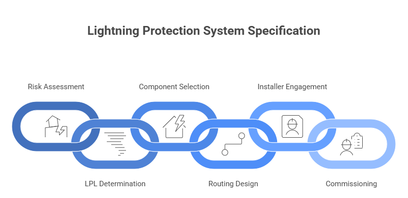
| Step 1 | Conduct a Risk Assessment Use the IEC 62305-2 framework to quantify risk from direct strikes, flashover, and LEMP. Calculate annual loss of human life and economic loss for your specific structure and location. |
| Step 2 | Determine Required LPL Based on risk assessment output, identify whether LPL I, II, III, or IV is required. The LPL dictates all dimensional parameters for the system design. |
| Step 3 | Select Certified Components Every component — air terminals, conductors, clamps, earthing electrodes — must be tested to IEC 62561. Do not substitute unrated components even at ‘equivalent’ dimensions. |
| Step 4 | Design the Routing Map down conductor routes to avoid sharp bends (minimum 20 cm bend radius), maintain required separation distances from metallic services, and minimise conductor length. |
| Step 5 | Engage a Qualified Installer Installation should be carried out by a certified lightning protection specialist. Installers should provide documentation of each earth resistance measurement taken. |
| Step 6 | Commission and Document A full commissioning test including earth resistance measurements at each electrode, conductor continuity checks, and a test certificate should be issued on completion. |
When to Consult a Specialist vs. a Supplier
For complex or critical facilities (hospitals, data centres, explosive environments, heritage buildings), engage an independent lightning protection consultant before approaching any supplier. A consultant’s role is to produce the risk assessment and system specification without a commercial interest in the components you purchase.
For straightforward commercial or residential buildings, a reputable specialist installer with demonstrable experience in IEC 62305 or NFC 17- 102 design can typically carry out both the specification and installation. Request evidence of professional accreditation and previous project references.
Conclusion: Protection Is a System, Not a Product
The most important thing to take away from this guide is the word system. A lightning rod alone is not lightning protection. A down conductor alone is not lightning protection. An earthing electrode alone is not lightning protection.
A complete, certified lightning protection system — where every component is correctly specified, manufactured, and installed to relevant standards and regularly measures available to building owners and operators. Unlike fire sprinklers, it requires no water supply. Unlike alarm systems, it requires no power. It functions instantaneously, passively, and indefinitely — provided it is maintained.
The cost of installing a compliant system on a new commercial building is typically a fraction of a percent of the construction value. The cost of a single unprotected strike event — in structural damage, equipment loss, data recovery, business interruption, and potential liability — routinely exceeds it by orders of magnitude.
If you are reading this because you are responsible for a building, the next step is straightforward: commission a formal risk assessment. It will either confirm that you are already protected, tell you what level of protection you need, or confirm that your existing system is compliant. Any of those three outcomes is more useful than continuing without one.
