Every monsoon season, India’s newspapers carry the same grim statistics. According to the National Crime Records Bureau, lightning strikes kill more people in India than any other weather event — over 2,500 fatalities annually, with many more injuries and significant damage to buildings, electrical infrastructure, and telecommunications equipment. Most of these incidents are preventable. The technology to protect structures from direct lightning strikes has existed for over 270 years. It is called a lightning conductor — and in 2025, there is no engineering justification for a commercial or industrial building to be without one.
This guide explains what a lightning conductor is, how it works, the types available, and what the current installation standards (IEC 62305 and NFC 17-102) require.
What Is a Lightning Conductor?
A lightning conductor (also called a lightning rod, air terminal, or strike termination device) is a metal rod or conductor mounted preferably at the highest point of a structure and connected via a low-impedance conducting path to an earth termination network buried in the ground. Its purpose is to intercept lightning strikes before they can discharge into the structure itself, and to safely conduct the enormous electrical energy of a lightning discharge — typically 1 to 5 gigajoules, delivered in 30–50 milliseconds — through a defined, engineered path to earth, where it dissipates harmlessly into the soil.
In simpler terms, a lightning conductor gives lightning somewhere safe to go, so it does not go through your building, your electrical systems, or the people inside.
The concept was first demonstrated by Benjamin Franklin in 1752. The physics have not changed. The engineering standards, materials, and installation methodology have evolved considerably since.

How Does a Lightning Conductor Work?
Understanding the working principle of a lightning conductor requires understanding how lightning forms and how it chooses its strike point.
The Physics of a Lightning Strike
Lightning begins in a storm cloud, where turbulent air separates electrical charge. Negative charge accumulates at the base of the cloud, positive charge at the top. As the charge differential grows, the electric field between the cloud base and the ground beneath it intensifies. At a threshold field strength — typically around 3 million volts per metre — the air breaks down and begins to ionise, forming a conducting channel.
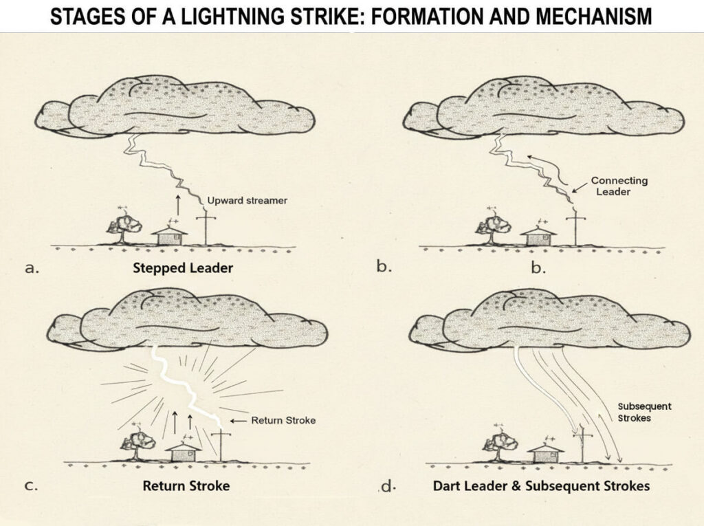
This channel develops in stages:
- Stepped leader — An invisible, branching channel of ionised air propagates downward from the cloud in discrete steps of approximately 50 metres, often pausing to recharge between steps.
- Upward streamer — As the stepped leader approaches within 50–100 metres of the ground, the concentrated electric field at tall or pointed objects on the ground becomes sufficient to launch upward-propagating streamers of ionised air.
- Connection — When a stepped leader connects with an upward streamer, the full discharge channel is established — the return stroke
- Return stroke — The visible flash: a discharge of up to 30 kA (typical) or 200 kA (extreme) travels back up the now-complete channel at roughly one-third the speed of light, releasing the stored charge as light, heat, and electromagnetic energy.
The lightning conductor exploits step 2. By placing a pointed conductor at the highest point of the structure — where the electric field concentration is naturally greatest — it ensures that the upward streamer that forms there is the one most likely to connect with the descending stepped leader. The strike terminates at the rod, not at the building.
The Conducting Path to Earth
Intercepting the strike is only half the job. Once the lightning current — which can reach 200 kA in a direct strike — enters the lightning rod, it must be conducted to earth through a path with low enough impedance that dangerous side-flashing (the current jumping to other nearby conductors or structural elements) does not occur.
This requires:
- A down conductor of adequate cross-section (minimum 50 mm²) that carries the full discharge current without melting or generating dangerous magnetic fields.
- An earth termination network — buried rod electrodes and connecting conductors — with low enough resistance (ideally < 10 Ω per, < 1 Ω for substations) to dissipate the current into the soil without dangerous step-potential gradients at the surface.
The complete system — air terminal + down conductor + earth termination — is a Lightning Protection System (LPS), and each component must be engineered as part of a coordinated design, not assembled from unmatched parts.
Types of Lightning Conductors
Not all lightning conductors are the same. The type specified depends on the structure’s risk category, height, plan area, and the required protection level.
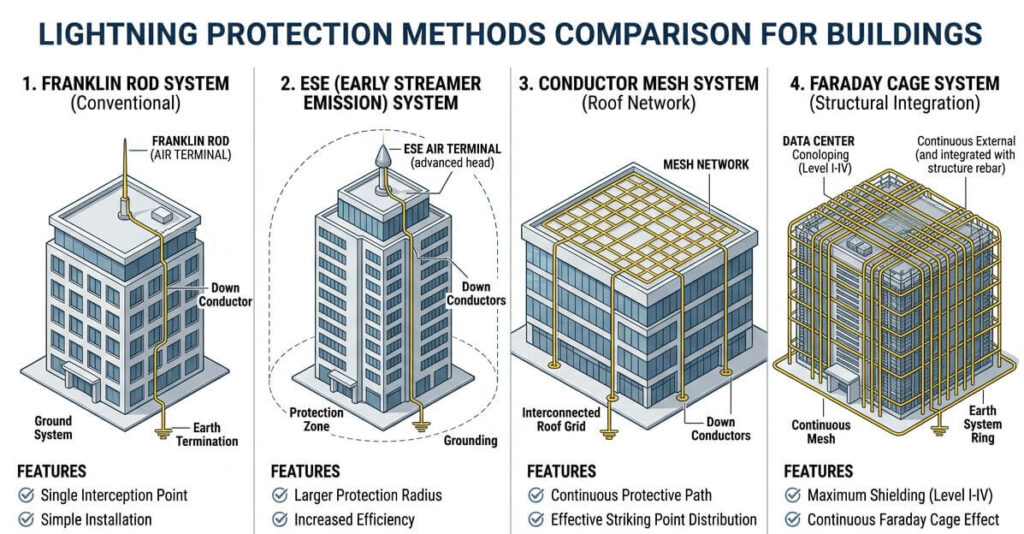
1. Franklin Rod (Conventional Lightning Rod)
The original — and still the most widely used — air terminal. A simple pointed copper, aluminium or steel rod mounted at the apex of the structure. Franklin rods operate on the passive principle: they enhance the naturally occurring upward streamer from the structure’s highest point, providing a defined and favourable point of connection for the descending stepped leader.
Best for: Residential buildings, small commercial structures, factory rooftops, telecom towers
Protection radius: Defined by the rolling sphere method (IEC 62305) or the angle of protection method — a 45° protection angle at LPL III-IV, 30° at LPL II, 20° at LPL I
HEX supply: View HEX Lightning Protection System components →
2. Early Streamer Emission (ESE) Air Terminal
ESE air terminals are an active variant that emit an upward streamer earlier — and therefore with a greater advancement distance — than a conventional Franklin rod. The benefit is a larger protection radius from a single terminal, reducing the number of terminals required on large structures.
Best for: Large-footprint structures where fewer terminals are commercially attractive
Design standard: NFC 17-102 / UNE 21186
3. Conductor Tape Air Terminal (Horizontal Conductor / Mesh System)
Rather than discrete point rods, the mesh system creates a network of horizontal metal tape conductors across the roof surface, forming a conducting cage that intercepts strikes across the entire roof area rather than relying on individual point rods to provide angular coverage.
Best for: Flat-roofed buildings, warehouses, data centres, and structures with many rooftop services where point rods would be impractical to install without obstructing equipment
Mesh size: Determined by the required LPL — 5×5 m (LPL I), 10×10 m (LPL II), 15×15 m (LPL III), 20×20 m (LPL IV)
Down conductors: Placed at building corners and at maximum 10–20 m intervals along façade.
Design standard: IEC 62305
4. Faraday Cage (Full Cage System)
The most comprehensive form of LPS — a complete conducting enclosure of the structure using air terminals, horizontal conductor tape on the roof, vertical conductors down the façade, and a perimeter earth ring. Named for Michael Faraday’s discovery that the interior of a conducting shell is shielded from external electric fields.
Best for: Critical infrastructure — data centres, hospitals, substations, explosive storage, heritage buildings
Standard: IEC 62305-3, LPL I (highest protection level)
Components of a Lightning Protection System
A complete Lightning Protection System per IEC 62305 consists of four integrated subsystems:
| Component | Function | HEX Products |
| Air termination network | Intercepts the lightning strike at the top of the structure | Franklin rods with single or multiple points, ESE lightning arrestors, mesh conductors, metallic & non-metallic clamps & connectors. |
| Down conductor system | Carries the lightning current from the Air termination network to the earth termination system | Copper, aluminium or copper-bonded-steel tape or round conductors, insulated cables, metallic & polymer clamps & connectors, test links, Lightning strike counters. |
| Earth termination network | Dissipates the current safely into the soil. | Copper or copper bonded steel rods, pipe or plate earthing electrodes, clamps & connectors, Ground enhancing compounds, ready-to-use polymer & concrete earth pit chambers, exothermic welding systems. |
| Bonding and surge protection | Prevents side-flashing; protects connected electrical & electronic systems | Equipotential bonding bars & braids, Surge Protection Devices (SPD’s). |
Each component is subject to minimum cross-section, material, and installation requirements specified in IEC 62305-3 or NFC 17-102. The system fails at its weakest component — a correctly sized air terminal connected by an undersized or poorly earthed down conductor provides no reliable protection.
Explore HEX’s complete Earthing & Lightning Protection product range →
Lightning Conductor vs Lightning Arrester
These two terms are frequently confused — and the confusion can have serious consequences for system specification.
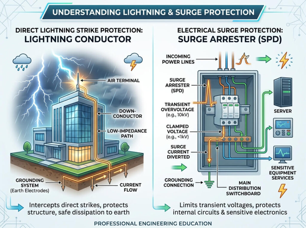
| Lightning Conductor/Arrestor | Lightning Surge Arrester | |
| What it does | Intercepts and conducts direct lightning strikes to earth | Clamps transient overvoltages on electrical conductors caused by lightning |
| What it protects | The structure itself — building, roof, fabric | Electrical equipment — transformers, switchgear, cables, electronics |
| Where it is installed | On the structure exterior — roof, mast, façade | On electrical lines — at transformer terminals, panel incomer, cable entry points |
| Relevant standard | IEC 62305, NFC 17-102, IS 2309 | IEC 60099-4, IS 3070 |
The critical point: a lightning conductor alone does not protect a building from a direct lightning strike. A lightning surge arrester alone does not protect the electrical systems inside from the transient overvoltages induced by a nearby strike. A complete protection strategy requires both the conductor for structural protection and the surge arrester for equipment protection — coordinated within the overall LPS design.
Installation Standards: IEC 62305 & NFC 17-102
IEC 62305: International Standard for Lightning Protection
IEC 62305 is the international standard family governing lightning protection system design, installation, and inspection. It consists of four parts:
- IEC 62305-1: General principles — the physics of lightning, risk parameters, damage categories
- IEC 62305-2: Risk management — a structured methodology for calculating the tolerable risk of loss for a structure and determining whether protection is required, and to what level.
- IEC 62305-3: Physical damage to structures and life hazard — design requirements for the external LPS (air terminals, down conductors, earth termination)
- IEC 62305-4: Electrical and electronic systems within structures — internal LPS (bonding, shielding, surge protection devices)
Lightning Protection Levels (LPL) defined in IEC 62305 determine the design parameters:
| LPL | First Return Stroke Peak Current (kA) | Typical Structure Type |
| I (highest) | 200 kA | Hospitals, data centres, explosive storage, heritage |
| II | 150 kA | Industrial facilities, hotels, shopping malls |
| III | 100 kA | Residential buildings, schools, offices (>20m) |
| IV (lowest) | 100 kA | Small residential, temporary structures |
NBC 2016: National Building Code of India
The National Building Code 2016 (Part 8, Section 6) mandates lightning protection for specified categories of structures in India, including:
- Buildings exceeding 15 metres in height
- Buildings containing explosive, flammable, or hazardous materials
- Structures in areas of high lightning incidence (keraunic level > 30 thunderstorm days per year — which covers most of India)
- Telecom towers, industrial chimneys, and electrical substations
NBC 2016 references both IS 2309 (Indian Standard for Protection of Buildings and Allied Structures Against Lightning) and IEC 62305 for system design methodology. For projects requiring NBC compliance, the risk assessment methodology of IEC 62305-2 is the appropriate tool for determining the required LPL.
Indian context: Given India’s high thunderstorm incidence — many parts of Maharashtra, Odisha, Jharkhand, and the eastern states experience 40–70+ thunderstorm days per year — the risk threshold for requiring LPS is reached quickly. Any commercial or industrial structure above 15 metres in these regions should be subject to a formal IEC 62305-2 risk assessment.
Yes. Lightning conductor, lightning rod, air terminal, and strike termination device are all terms for the same component — the pointed conductor mounted at the structure’s highest point that intercepts lightning strikes. “Lightning conductor” is the more commonly used term in British and Indian English; “lightning rod” is more common in American usage.
This is a common misconception. A lightning conductor does not increase the probability of a strike occurring in the area — lightning strikes where the stepped leader and upward streamer connect, which is determined by the storm’s charge distribution and the local topography, not by the presence of a rod. What the conductor does is ensure that if a strike occurs at or near the structure, it has a defined, safe path to earth rather than finding its own path through the building fabric, electrical wiring, or plumbing.
IEC 62305-3 recommends visual inspection every 12 months and full testing (including earth resistance measurement) every 24 months for LPL I and II systems, and every 48 months for LPL III and IV. After any confirmed or suspected strike, the system should be inspected immediately, regardless of the scheduled inspection interval.
IEC 62305-3 specifies that the earth resistance of the LPS earth termination network, measured individually before interconnection, should not exceed 10 Ω for each down conductor termination. For complete building earthing systems integrating both LPS and electrical system earthing (combined earthing), IS 3043 specifies ≤ 1 Ω for critical facilities.
Yes. Retrofit installation is entirely feasible and is the most common scenario in India — most existing building stock predates the current NBC 2016 requirements. Retrofit LPS design requires a site survey to map the roof geometry, structure height, and existing electrical installation, followed by a risk assessment per IEC 62305-2 to determine the required protection level. HEX can supply all hardware for retrofit LPS installations. Contact our technical team for a supply enquiry →
Conclusion
A lightning conductor is not a luxury or an optional enhancement for large structures — it is a fundamental life-safety and asset-protection system that every commercial, industrial, and infrastructure building above 15 metres in India should have, and that many smaller structures in high-keraunic regions also require. The technology is mature, the standards are clear, and the installation is straightforward when designed and executed correctly.
The key principles to carry away: size your LPS to the correct Lightning Protection Level for the structure and its risk profile; ensure the air termination, down conductor, and earth termination are all designed as an integrated system; combine the structural lightning conductor with appropriately specified lightning arresters to protect the electrical and electronic systems inside; and inspect it.
HEX Worldwide supplies complete lightning protection system hardware — air terminals, down conductors, ground rod clamps, copper bonded earthing rods, and exothermic welding systems — for new build and retrofit LPS installations across India. View our Earthing & Lightning Protection range → or contact our applications team for project-specific technical support.
