
Every year, lightning causes thousands of deaths in India. In NCRB’s 2024 snapshot, lightning accounted for 35.7% of 7,903 accidental deaths attributed to forces of nature—roughly 2,800 deaths when calculated from the reported share. These are fatality figures, not a count of all injuries or property damage. NCRB, Accidental Deaths & Suicides in India 2024
A properly designed lightning protection system (LPS) can reduce certain risks to a building and its occupants. It cannot stop a thunderstorm, guarantee that a building will never be struck, or make every lightning hazard disappear. Protection depends on the building, its use, local lightning exposure, the applicable rules and standards, and a suitable engineering design.
This guide explains what a lightning conductor is, how a lightning protection system works, the main design approaches, and the standards and Indian regulations to check. It is an introduction—not a substitute for a project-specific risk assessment or design by a qualified professional.
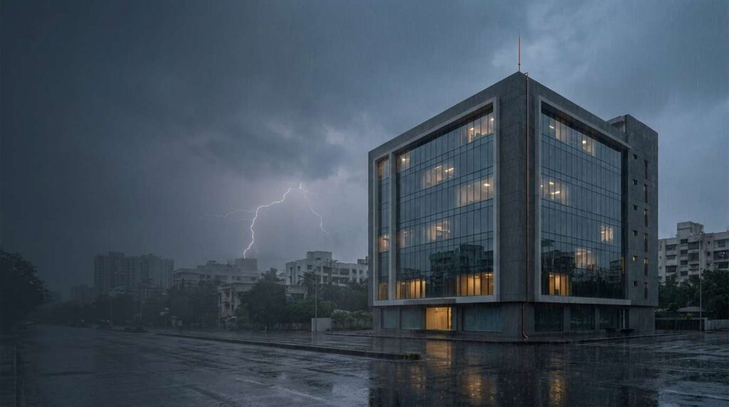
An external lightning-protection system is designed to reduce risk; it does not prevent storms or guarantee that damage cannot occur.
What is a lightning conductor?
In everyday Indian and British English, lightning conductor is often used to mean a lightning rod. In technical writing, it helps to distinguish the parts:
- An air terminal (sometimes called a lightning rod or strike-termination device) is the exposed metal part positioned to intercept a direct strike.
- A down conductor carries lightning current from the air-termination network toward the earth-termination system.
- The earth-termination system—electrodes, ring conductors, foundation electrodes or a designed combination—provides paths for current to spread into the ground.
- Bonding and surge-protection measures help control dangerous potential differences and protect electrical and electronic systems.
Together, these coordinated measures form a Lightning Protection System. A single pointed rod is not, by itself, a complete building LPS.
Benjamin Franklin’s experiments in the 1750s helped establish the electrical nature of lightning and inspired the lightning rod. The famous 1752 experiments and early lightning-rod installations mark the beginning of this technology, although the modern system is far more than a rod and wire. Smithsonian, “Electrical Years: Part 2” Founders Online, Franklin’s 1752 account
How does a lightning protection system work?
A simplified picture of a cloud-to-ground flash
Charge separation within a thunderstorm creates a strong electric field. In a common negative cloud-to-ground flash, a faint, branching stepped leader advances downward in short steps—often around 50 metres each. As it approaches the ground, upward streamers may develop from objects below. When one connects with the descending leader, a conducting channel is established. The bright return stroke then propagates upward through that channel. A flash may contain more than one leader–return-stroke sequence. NOAA/National Weather Service: stepped leaders and return strokes NWS: return stroke
A typical cloud-to-ground return stroke has a peak current of roughly 30 kA, though values vary widely and exceptional strokes can be much higher. The often-quoted 200 kA figure is an extreme design-scale value, not a typical strike. The short, high-current impulse must not be confused with the longer time over which a complete lightning flash develops. NWS: lightning power
Interception and the path to earth
A conventional air-termination system is positioned using recognised protection methods—such as the rolling-sphere, mesh or protection-angle method—rather than by assuming that one rod at the highest point guarantees protection. Correctly placed terminals and conductors provide a preferred attachment point within the designed protection zone. They reduce risk; they do not guarantee that every nearby strike will attach to a particular rod.
If lightning attaches to the LPS, the down-conductor network is designed to carry the current toward the earth-termination system. The path must be continuous, appropriately sized, routed and bonded. Poor routing, discontinuous connections, inadequate separation or unbonded metalwork can contribute to side-flashing and dangerous potential differences.
The current spreads through the earth-termination arrangement and surrounding soil. This does not mean the strike becomes harmless: touch and step voltages, fire, side-flash and damage to connected equipment remain possible. Good design aims to reduce those hazards through current distribution, bonding, separation and coordinated surge protection—not through one earth-resistance number alone.
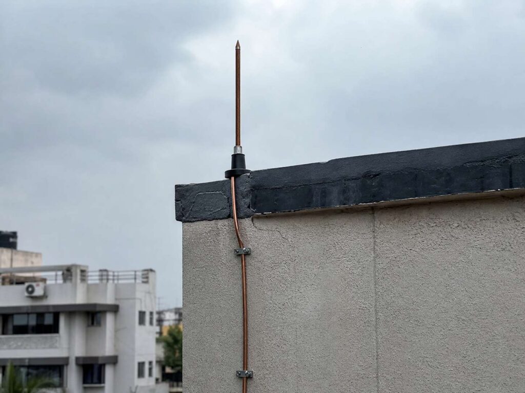
Illustrative rooftop hardware; actual placement and materials must follow the project design and applicable standard.
Main lightning-protection approaches
1. Conventional air terminals (Franklin rods)
A conventional air terminal is a metal rod or terminal connected to the rest of the external LPS. It is a passive component; its position and the protection zone are determined by the design method and the structure’s geometry.
Often considered for: houses, commercial buildings, industrial roofs, masts and towers—when the risk assessment and design call for them.
Important: There is no universal protection radius for a single rod. Under IEC 62305, terminal placement depends on the selected LPS class, terminal height and the chosen geometric method. A single fixed “45-degree zone” should not be assumed for all buildings.
2. Early Streamer Emission (ESE) terminals
ESE terminals are designed and evaluated under NF C 17-102, a French standard that specifies an ESE testing and protection-radius method. The method uses a measured time-advance value and claims a larger protection radius than a conventional terminal of comparable height.
That claimed enlarged radius is not the IEC 62305 design method, and the performance advantage of ESE systems under natural lightning conditions remains contested. NF C 17-102 and IEC 62305 are distinct design bases; they should not be treated as interchangeable. Before specifying ESE, confirm acceptance with the authority having jurisdiction, client, insurer and project engineer, and document the governing standard. AFNOR: NF C 17-102 IEC 62305-3:2024
3. Roof mesh or conductor network
A mesh system uses interconnected horizontal conductors across a roof, connected to down conductors and an earth-termination system. It can suit large, flat roofs, including warehouses and roofs with many services, but equipment layout, clearances, bonding and maintenance access still need to be designed.
The familiar IEC mesh dimensions associated with LPS classes I–IV are shown below. These are design limits, not a substitute for checking the air-termination layout against the whole structure and the edition adopted for the project.
| LPS class | Rolling-sphere radius | Maximum mesh dimension |
|---|---|---|
| I | 20 m | 5 × 5 m |
| II | 30 m | 10 × 10 m |
| III | 45 m | 15 × 15 m |
| IV | 60 m | 20 × 20 m |
The classes use preferred down-conductor spacings of 10 m, 10 m, 15 m and 20 m respectively (I to IV). These are preferred design values, not a blanket maximum for every building. Corners and the building perimeter also matter. Confirm placement and any permitted adjustments in the applicable edition of IEC 62305-3. IEC 62305-3:2024
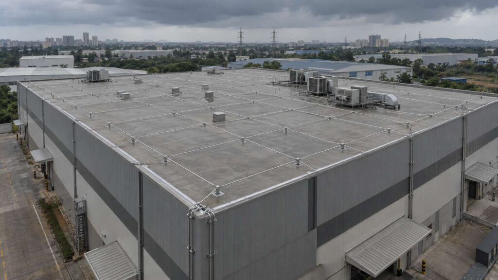
Mesh layout is a design method—not a substitute for detailed checks of the roof, equipment, bonding and conductor routes.
4. Mesh or “Faraday cage” arrangement
A roof mesh, perimeter conductors and multiple down paths may form a cage-like external LPS around a structure. “Faraday cage” is often used informally for this approach, but it is not a separate protection class and does not guarantee that the interior is immune from every lightning effect. The internal electrical and electronic systems still need an appropriate surge-protection and bonding strategy.
The required LPS class is not determined by building type alone. A hospital, data centre, school or industrial facility does not automatically require LPS class I. The required protection follows the risk assessment and any applicable code, permit, contract or sector-specific rule.
What makes up a complete LPS?
| Part | What it does | Examples of items to specify |
|---|---|---|
| Air-termination network | Provides designed strike-attachment points and coverage | Rods, roof conductors, mesh and compatible connectors |
| Down-conductor system | Carries current toward the earth-termination system | Conductors, clamps, bonds, test joints and—where used—strike counters |
| Earth-termination system | Provides an engineered route for current to disperse into the ground | Ring or foundation electrodes, rods, connections and inspection points |
| Internal protection measures | Limit dangerous potential differences and reduce surge effects inside | Equipotential bonding, separation, shielding, cable routing and coordinated SPDs |
Conductor dimensions depend on material, form, mechanical and thermal requirements, the applicable standard and the component specification. Do not apply one cross-section figure to copper, aluminium and steel alike. IEC 62305-3 covers LPS design and installation; the IEC 62561 series specifies requirements for lightning-protection-system components. IEC 62305-3:2024 IEC TC 81 publications
HEX’s product range: Earthing & lightning protection →
Lightning conductor vs. Surge arrester
These terms are often mixed up. Use air terminal for the external strike-interception component and surge protective device (SPD) for a device installed on electrical or communication circuits to limit transient overvoltages.
| External lightning-protection system | Surge protective device (SPD) | |
|---|---|---|
| Main purpose | Reduce physical damage and life hazards from direct lightning attachment to a structure | Limit transient overvoltages on connected electrical/electronic systems |
| Typical location | Roof, building exterior, mast and earth-termination system | Power, data or signal circuits at suitable entry points and equipment locations |
| Does not replace | Internal surge protection and bonding | An external LPS designed for direct-strike protection |
| Relevant framework | IEC 62305-1/-3 and applicable national rules; NF C 17-102 only when its ESE method is accepted | IEC 62305-4 and relevant SPD product/application standards |
A coordinated strategy may need both an external LPS and SPDs. Properly selected and installed SPDs are intended to limit conducted and induced surges, including those associated with nearby lightning, but no single device protects every circuit under every event. The external LPS does not by itself ensure that all internal electronics are protected. IEC 62305-4:2024
HEX product links: Lightning conductor system →
Standards and Indian requirements
IEC 62305:2024
The current international IEC 62305 series is the 2024 third edition. Its four parts cover:
- IEC 62305-1: General principles.
- IEC 62305-2: Risk management.
- IEC 62305-3: Physical damage to structures and life hazard, including the external LPS.
- IEC 62305-4: Electrical and electronic systems within structures and surge-protection measures.
The IEC Webstore records the 2024 editions as replacing the 2010 editions. Projects in India should confirm the corresponding IS/IEC adoption and edition specified by the authority, contract or project documents rather than assume every local reference has automatically been updated. IEC Part 1 · Part 2 · Part 3 · Part 4
An IEC risk assessment considers the structure, use, occupancy, contents, incoming services, local lightning exposure and possible consequences. It informs whether protection measures are needed and helps determine the protection level. Do not choose a protection class solely from a generic list of “typical buildings.”
NF C 17-102 and ESE systems
NF C 17-102 is a French standard specifically associated with ESE systems. It defines its own ESE-specific test and protection-radius method. It is not another name for IEC 62305, and its claimed larger-radius method should only be used where the project’s rules and stakeholders accept it. AFNOR NF C 17-102
What Indian building owners should check
The Central Electricity Authority (Measures relating to Safety and Electric Supply) Regulations, 2023, Regulation 38, addresses electrical safety measures for multi-storey buildings over 15 m and specified premises, including airports, hospitals, hotels, places of entertainment and worship, cultural centres, stadiums, academic buildings, test labs, industrial installations and premises with explosive or flammable material. Among its measures, it states that building lightning protection is to be as per the relevant standards. Check the official regulation and the requirements that apply to the specific project. CEA official regulation page Gazette of India text
The National Building Code of India (NBC) 2016 is a model code; its legal effect depends on adoption through applicable rules, approvals or contractual requirements. Its electrical-installation provisions are in Part 8, Section 2. Confirm the local building bye-laws, state electrical rules, fire approvals, sector-specific regulations and project specifications. BIS guide for using NBC 2016
Do not use a single “thunderstorm days per year” threshold as a substitute for a site-specific assessment. Modern risk methods use lightning-exposure data and structure-specific factors; choose suitable local data and the method required by the governing standard.
Design note: IS 2309:1989 is an older standard and is listed as withdrawn/superseded. Confirm the current Indian Standard and edition required for the project before citing IS 2309 as a governing standard. IS 2309 status record
Inspection, testing and earthing: avoid one-number rules
A lightning protection system should be inspected and maintained, but there is no single interval that is appropriate for every building and every jurisdiction. Set a documented schedule using the applicable edition of IEC 62305-3, the risk and use of the building, local regulations, environmental conditions, system condition and manufacturer guidance. Have the system checked after a known strike, physical damage, repair, rooftop modification or other material change. The current IEC standard covers inspection and maintenance; the precise regime should be checked in the edition adopted for the project. IEC 62305-3:2024
Likewise, 10 Ω is not a universal pass/fail value for every down conductor or every LPS earth electrode under IEC 62305. A low earth resistance is often desirable, but electrode arrangement, bonding, current distribution, touch/step potential and soil conditions also matter. IS 3043 does not create a universal “1 Ω for every building” rule; substation targets are specific to the installation and its safety design. Use the target required by the governing standard and project design, and interpret measurements in context. IS 3043:2018 record
Frequently asked questions
Is a lightning conductor the same as a lightning rod?
In everyday usage, often yes. More precisely, a rod is one type of air terminal; “lightning conductor” may also be used for the connected conducting path or the system more broadly. Use air terminal when referring specifically to the strike-interception component.
Does a lightning rod attract lightning and make a building more dangerous?
A rod does not create thunderstorms or increase lightning activity across a region. It is intended to provide a preferred attachment point within the system’s designed protection zone. It does not ensure that every nearby strike will hit the rod, nor does it eliminate all risks to a building.
How often should an LPS be inspected?
Use the schedule required by the applicable standard, local regulations and project risk assessment. Inspection frequency depends on the structure, system class, exposure, environment and system condition. Arrange an additional inspection after a known strike, damage, repair or material change.
What earth resistance should a lightning protection system achieve?
There is no universal single number that establishes safety for every lightning-protection earth. Follow the governing standard and project specification, and assess the earth-termination arrangement together with bonding, current paths and touch/step voltage considerations.
Can a lightning protection system be retrofitted?
Yes. Retrofit work is possible, but it needs a site survey of the roof and façade, structure, existing earthing and bonding, rooftop services, and electrical installation. A competent designer should assess risk, coordinate the external LPS with internal surge protection, and specify inspection and verification after installation.
Conclusion
A lightning conductor is one part of a coordinated lightning protection system—not a guarantee against every strike or every kind of damage. For a building in India, confirm the applicable CEA, state and local requirements; assess the structure and its use; select a recognised design basis; and coordinate air terminals, down conductors, earthing, bonding and surge protection.
For project-specific systems, use competent engineering design, compatible components and a documented maintenance plan. HEX supplies earthing and lightning-protection hardware for new-build and retrofit projects. Explore the Earthing & Lightning Protection range → or contact the applications team →.
Source list
- NCRB, Accidental Deaths & Suicides in India 2024 — Snapshots: official PDF
- NCRB 2023 lightning data, reported with table values: Down To Earth, 30 Sep 2025
- IEC official records: 62305-1:2024, 62305-2:2024, 62305-3:2024, 62305-4:2024
- Central Electricity Authority, Measures relating to Safety and Electric Supply Regulations, 2023: official Gazette PDF
- BIS, Guide for Using NBC 2016: official PDF
- AFNOR, NF C 17-102 listing: AFNOR Editions
- NOAA, stepped leaders and lightning process: NWS lightning science
- IS 3043:2018 status: BIS document record; IS 2309:1989 status: withdrawn/superseded record